
CNC Milling vs Alternatives: Choosing the Material–Process Pair That Wins Your Part
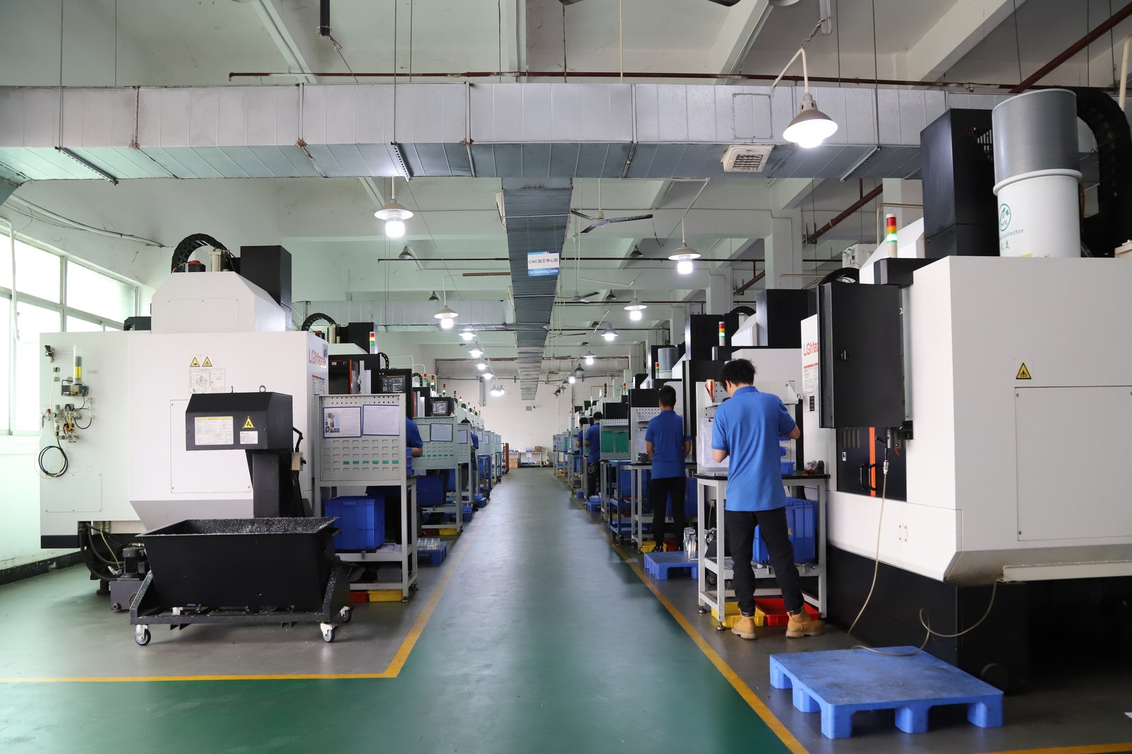
A prismatic part — a housing, a bracket, a plate with pockets and holes — can be produced several ways, and the way that wins is not the one with the best marketing. CNC milling cuts it from solid stock with a rotating cutter, which makes it the default for precision metal parts. But the same geometry can be printed in resin or metal powder, cast in aluminum, or molded in plastic, and each of those routes has a corner of the market where it genuinely beats the mill. The decision is a pairing problem: match the material and the process to the quantity you need, the tolerance the fit actually demands, and the stage your design is at. This guide is for the engineer or sourcing lead choosing between them. It sets out where CNC milling beats 3D printing, die casting, and injection molding, where it loses, and how to run the hybrid path most real products take — machine the development units now, tool the die or mold when volume proves out, and machine the critical features on the parts that follow.
What is CNC milling actually competing against?
Put the numbers on the table first, because they let you compare the processes honestly. CNC milling holds ±0.003 mm on critical features as a routine band on a disciplined floor, verified under statistical process control and on a CMM rather than by luck; precision grinding, where milling hands off a sealing or bearing surface, reaches ±0.002 mm. The alternatives build the same shape by a different mechanism, and the mechanism sets a tolerance ceiling no amount of tuning crosses:
- 3D printing stacks material in layers. Desktop FDM typically lands around ±0.3–0.5 mm; even industrial FDM struggles below ±0.1 mm. Resin printing reaches roughly ±0.1 mm, and SLS and metal printing sit in the ±0.1–0.2 mm band. The limits are physical — thermal shrinkage as each layer cools, stair-stepping at the surface, drift in a tall build.
- Die casting fills a steel die with molten aluminum or zinc. Parts repeat well from shot to shot, but the absolute band is looser than milling, porosity is a real risk in thicker sections, and the geometry must respect draft so that the part releases from the tool.
- Injection molding fills a steel mold with thermoplastic and typically holds ±0.1–0.5 mm depending on part size and resin. Plastic shrinks as it cools, and resins shrink differently — amorphous materials such as ABS move less than semi-crystalline ones such as POM.
A bearing seat, a sealing face, or a press-fit bore does not care which process made the part; it cares whether the surface is inside the band. When a drawing carries ±0.05 mm callouts or tighter, the interesting question is not which process to use but which features must be milled, because those features will be machined one way or another, even on a body that printing, casting, or molding produced.
Where does 3D printing genuinely win, and where does it lose to a mill?
Printing wins a narrow but real slice of the market. Use it for one to ten units of a geometry that would fight a mill — internal channels, lattices, organic curves, or a fit-and-form check while the design is still changing. Printing absorbs geometry changes for free, needs no tooling, and returns parts in hours to days, which is why it anchors early iteration. A single complex prototype printed overnight can save a week of waiting on a machined quote that would only confirm the design needs changing anyway.
Printing loses precisely where milling earns its keep. If the tolerance is ±0.003 mm or finer, printing cannot reach it — metal printing sits in the ±0.1–0.2 mm band, so any feature printed there must be machined afterward. When the part must carry load as real metal, a printed structure is layer-bound rather than isotropic solid stock, and thread-holding, fatigue, and strength pay for the difference. Where the surface must seal, mate, or look finished, the layer lines are a liability until a machining or finishing step removes them. And once volume climbs past the prototype stage, printed per-unit economics stay flat while a milled part's cost amortizes across the run. The mature pattern is a handoff, not a rivalry: print the complex prototype while the design settles, then mill the production part when tolerance, material, and strength are locked, and on any printed metal part, mill the critical faces.
When does a casting beat milling, and when is the tool a trap?
Die casting wins when three conditions line up: the geometry is a thin-wall housing, the volume is high enough to amortize a steel die, and the design is stable enough that a change will not send the die back for revision. The die is expensive and takes weeks, but once it exists the per-part cost drops below what a mill can reach, which is why the decision is an economic crossover rather than a quality argument.
Run the crossover before committing: tooling cost divided by the difference between the milled per-part cost and the die-cast per-part cost gives the quantity where the lines cross. For a stable aluminum housing that crossover typically sits in the thousands of parts — a few thousand for small pieces once you add design-change risk and tooling lead time to the raw math. Below the crossover, milling wins: a one-off, a bridge run, a spare, or a part whose envelope outruns a standard press is simply machined from plate or bar, and the same geometry can be prototyped on a mill now and migrated to casting later.
Quality cuts the other way too. A die-cast body is looser in tolerance, carries porosity risk in thicker sections, and is limited by draft. A design change after the die is cut is a mold revision, not a drawing note. That is why precision work on cast housings takes the hybrid shape: the die produces the thin-wall envelope and the low per-part cost, and the mill machines the bearing seats, sealing faces, and bolt patterns afterward at ±0.003 mm, verified on a CMM. Porosity and draft belong to the body; the tolerance belongs to the milling.
When does injection molding take the job, and what happens to tolerance?
Molding wins when the part is a thin-walled plastic enclosure, the design is frozen, and the volume is high enough that molded-in cosmetics and a low per-part cost outweigh the tooling. Once the mold exists, molding produces thousands of identical parts fast, and no subtractive process competes on that ground.
The mold, however, is a steel commitment that takes weeks while a mill ships first parts in days. And molding holds ±0.1–0.5 mm because of resin shrinkage — the tolerance of a plastic body, not of a precision feature. If your drawing is full of ±0.05 mm callouts, molding will not hold them. The engineering answer mirrors casting: a molded body with milled critical faces. The plastic enclosure provides the geometry and the finish; the bore that locates a bearing, the seat that seals, or the insert that carries a thread is milled after molding. That is how a plastic part holds a real seat.
Do not treat these processes as rivals to be picked once. They are tools with different cost curves, and the winning configuration for most products is sequential: mill the development units now to feed validation while the mold is cut in parallel, then mold for steady-state volume and mill the critical features on the molded parts.
Which material–process pair wins — a decision table for milled parts
Start from the requirement that dominates your part, not from the process you already know. This table is the working version of the whole argument.
| If your part is… | The material–process pair that wins | Why |
|---|---|---|
| One to ten complex pieces, design still moving, fit-and-form check | 3D printing prototype, then CNC milling for the production version | Printing absorbs geometry changes and ships in hours; milling holds the tolerance the released design needs |
| A metal part with ±0.003 mm features, true stock properties, or thread-holding | CNC milling from plate, bar, or billet | Milling cuts any machinable stock from solid isotropic material and holds the tight band |
| A thin-wall aluminum housing headed for high volume | Die-cast body with milled critical features | The die gives the envelope and low per-part cost; milling holds the seats, bosses, and bolt patterns |
| A plastic enclosure at stable high volume | Molded body with milled critical faces | Molding gives thin-wall geometry and molded-in finish; milling holds the real seats |
| Any part whose drawing has not been reviewed | CNC-milled prototype at MOQ 1 with a DFM review before any tooling decision | The cheapest place to find a datum problem or an over-toleranced feature is before the die or mold exists |
Quantity does the heavy lifting. Below a few hundred pieces, no tooling-heavy process pays for itself, and CNC milling — with no tool, a minimum order of one, and per-part cost that stays roughly flat because it is setup-dominated — is the honest default. Above a few thousand stable parts, the die or mold starts to earn its keep. Between the two sits the hybrid zone, where the answer is usually "mill now, tool later."
How do you run the hybrid path without managing three suppliers?
A hybrid only works when the handoffs are clean, and that is a supply-chain question as much as an engineering one. Milling a prototype is a one-day conversation with a shop that reads GD&T and returns a design-for-manufacturing review. Handing a printed, cast, or molded body to a different shop that must machine its critical faces is a second qualification with new risks — datum interpretation, material unknowns, coating surprises. A supplier that runs CNC milling in-house and sources the complementary process through vetted partners keeps the sequence under one quality system: the same team reads the drawing, the same metrology verifies the result, and the printed prototype and the milled production part are held to the same standard.
The practical sequence on the floor behind this site starts with the drawing. Send the model and toleranced 2D print for a DFM review and a quote; milling starts from one piece at MOQ 1, on the same machines and tolerances as production, with lead tiers of roughly 3, 7, or 30 days depending on complexity. Iterate the prototype while the design settles. When volume and geometry prove out, the die or mold is cut — through a vetted partner for plastic molding or cast housings — and the critical features on the bodies that follow are milled on the same floor and verified on the same CMMs. One drawing, one quality system, no lost handoff.
The detail behind each comparison lives in the pages that sit under it. The milling services overview explains the axis-count decision and what each process holds; the parts guide covers the material list and the DFM rules that keep a milled part machinable. The milling cost model shows how the quote is structured and where crossover thinking belongs in your budget, and the aluminum milling guide covers the most common milled metal in depth. Start there, then send the drawing.
Frequently Asked Questions
Can 3D printing match CNC milling tolerances?
No. Printing typically holds ±0.1–0.5 mm depending on the technology — desktop FDM around ±0.3–0.5 mm, resin around ±0.1 mm, SLS and metal printing in the ±0.1–0.2 mm band — while CNC milling holds ±0.003 mm routinely. When microns are required on a printed part, the critical faces are milled after printing.
When is die casting cheaper than CNC milling?
Above the crossover volume, where the die cost is amortized across enough units that the low per-part cost beats milling — typically a few thousand parts for small aluminum housings once design risk and tooling lead time are added. Below that, or for prototypes, spares, and bridge runs, milling from plate or bar is the economical route.
When should I use injection molding instead of CNC milling?
When the design is stable, the volume is high, and the part is a thin-walled plastic enclosure with molded-in finish. Molding holds ±0.1–0.5 mm because of resin shrinkage; a part full of ±0.05 mm callouts still needs milling — either as a CNC part or as a molded body with milled critical faces.
Can I prototype in 3D printing and produce in CNC milling?
Yes, that is the standard bridge. Print the complex prototype while the design settles, then mill for production when tolerance, material, and strength are locked. On any printed metal part, mill the critical faces.
Do you offer 3D printing, casting, or molding alongside milling?
We mill in-house on a CNC floor holding ±0.003 mm, with precision grinding to ±0.002 mm for sealing and seating surfaces, and coordinate 3D printing, die casting, and injection molding through vetted partners — one quality system across the handoff, with critical features milled and verified on the same CMMs.
What tolerance can CNC milling actually hold?
Milling holds ±0.003 mm on critical features; precision grinding reaches ±0.002 mm for sealing and seating surfaces. Process capability is tracked at Ppk ≥ 1.67 at the initial study on key characteristics and Cpk ≥ 1.33 on general characteristics. Capability is reported per characteristic: every report names the feature, its tolerance band, the sample size, the sigma method, and the study window. Under SPC, and critical geometry is verified on CMMs against your datum scheme.
Which materials can be milled when the other process cannot?
If it comes as bar, plate, or billet, and it is machinable, it can be cut: aluminum, stainless, alloy steel, titanium, brass and copper, plus engineering plastics including PEEK and POM/Delrin. Every incoming lot is verified by XRF against its mill certificate before it reaches a machine.
Not sure whether your part should be milled, printed, cast, or molded?
Email the STEP or IGES model and toleranced 2D drawing to [email protected] or call +86 13126536955. You will get a design-for-manufacturing review that names the process path — including where a die or mold earns its keep, and which critical features should be milled regardless of the process that makes the body.