
- Sourcing CNC milling? Judge the shop on flatness, perpendicularity and positional tolerance across faces, because that is where a milled part fails, not on the dimensional number in the advert.
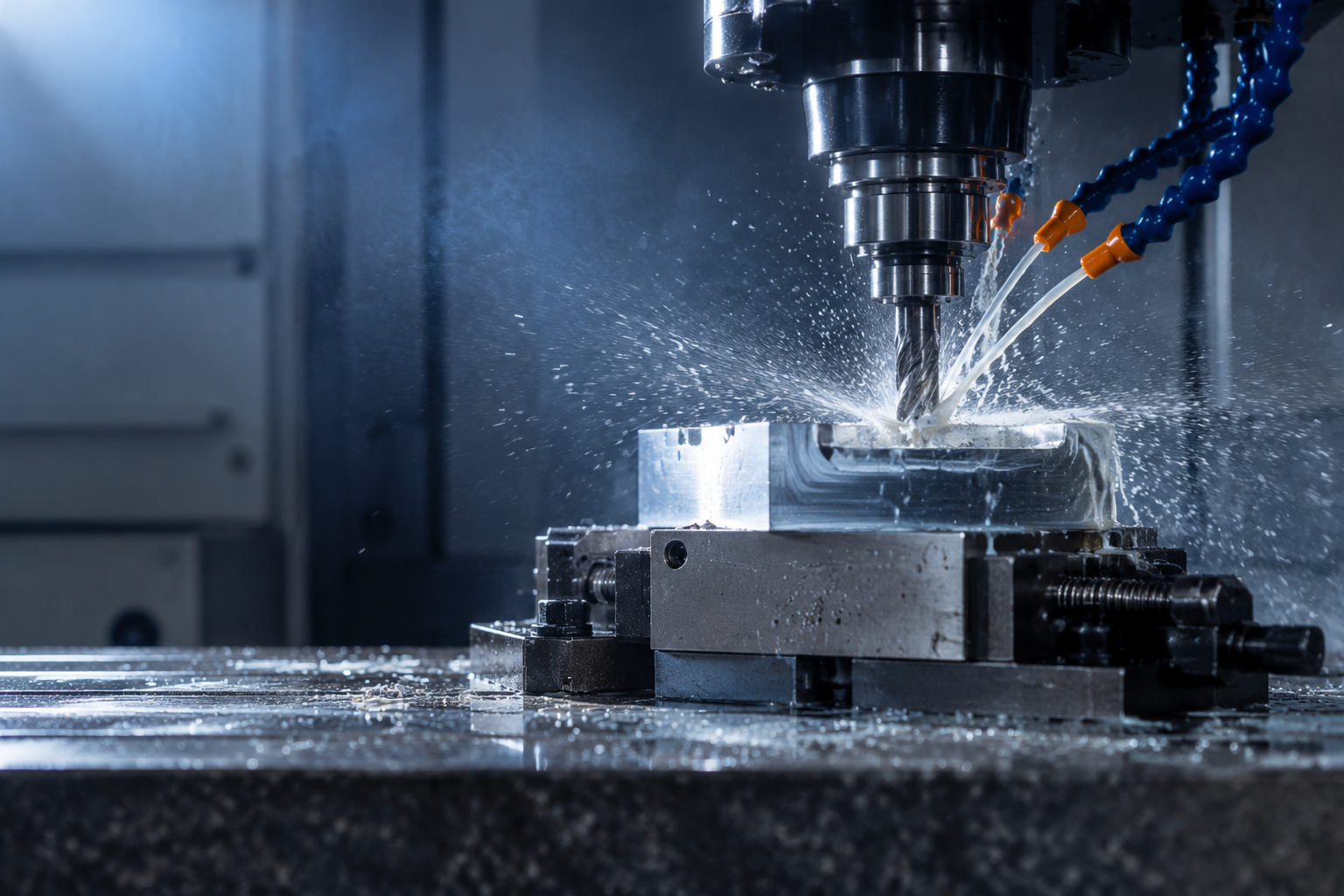
- What CNC milling is: the cutter spins and the workpiece is held still. That is how prismatic parts, pockets, slots and contoured faces get their shape, and why fixture strategy decides accuracy.
- 100+ production machines — Mazak / Brother / Tsugami / Star / Citizen class, across a 6,800 m² facility (3-axis 50+, 4-axis 20+, 5-axis 20+, 25+ lathes, 7+ grinders, 20+ inspection instruments).
- Held tolerances: ±0.003 mm, turning ±0.002 mm, grinding ±0.002 mm, each checked on Hexagon CMMs. Capability is stated per characteristic — Ppk ≥ 1.67 initially and Cpk ≥ 1.33 in production for key and special characteristics (≥ 1.33 general). Each report lists the feature, band, sample size, sigma method and study window.
- Certified under ISO 9001:2015, IATF 16949:2016 (design excluded) and ISO 14001:2015 — Dongguan Zhuohang Ltd is the invoicing entity behind them.
- Order terms: a one-piece minimum and lead times around 3, 7 or 30 days, set by part complexity.
| Category | Specification |
|---|---|
| CNC Milling Tolerance | ±0.003 mm |
| CNC Turning Tolerance | ±0.002 mm |
| Precision Grinding / Wire EDM | ±0.002 mm |
| 5-axis Machining Centres | Mazak VARIAXIS I-600, Mazak INTEGREX I-250H S (10+ machines) |
| Swiss-type Turning | TSUGAMI B0206-III / B0205-III, STAR SR-32JII / SR-32J Type N Type B, Citizen Cincom A20-3F7 (10+ lathes) |
| 3/4/5-axis Milling | Mazak / Brother / Sodick (50+ centres) |
| Wire EDM | 5+ machines |
| Inspection | Hexagon CMM + 20+ gauges (10:1 gauge rule) |
| Capability Indices | Ppk ≥ 1.67 initial / Cpk ≥ 1.33 production (key characteristics) |
| Materials | Aluminium, steel, stainless, titanium, brass, copper, Inconel, PEEK, Delrin |
| Certifications | ISO 9001:2015 (116024/A/0001/UK/En) · IATF 16949:2016 (131941/A/0001/SM/En, design clause 8.3 excluded) · ISO 14001:2015 (116024/B/0001/UK/En) |
| Legal Entity | Dongguan Zhuohang Ltd (USCC 91441900MA4UWT6X39, established 2005) |
| Plant | 6,800 m², 100+ CNC machines, Dongguan, China |
| MOQ / Lead Time | MOQ 1 piece · 3 / 7 / 30 days |
What is CNC milling?
CNC milling is a subtractive process in which a rotating cutter removes material from a fixed workpiece to produce prismatic shapes — housings, plates, brackets, pockets and slots. This Dongguan plant runs 3-, 4- and 5-axis milling centers and holds ±0.003 mm, verified on Hexagon CMMs. The machine type decides what geometry can be reached in how many setups.
CNC machining is the subtractive manufacturing of parts on computer-numerically-controlled milling, turning, and grinding equipment. A cutter removes material from a workpiece along a programmed toolpath to produce a part that meets a drawing-defined geometry, tolerance, and surface finish. "CNC" means the tool path is numerically controlled rather than hand-operated.
The rest of this guide turns that definition into a buyer's checklist for this shop — what to verify before you commit, and how the numbers on the drawing actually reach the part.
The discipline separates into milling (the cutter rotates and the workpiece is fed; prismatic geometry), turning (the workpiece rotates and the tool is fed; rotational geometry), and precision grinding / wire EDM (the tightest tolerances on critical features). A plant that produces CNC machined parts end-to-end runs all three.
The output of CNC machining is a part that meets the drawing — geometry, tolerance, surface finish, and material certificate — and is documented to a quality plan (FAI for general work, PPAP for automotive-bound parts, IMDS for material data). That is the answer to "what is CNC machining": a numerically-controlled subtractive process that produces a part to a drawing, with the quality documentation that lets the part enter an assembly.
What Are the Different Types of CNC Milling Machines?

Milling machines are defined by how many axes they can move and by the orientation of the spindle. The axis count is the first decision a buyer or designer makes, because it controls what geometry is possible and how many setups a part needs.
| Machine | Motion | Best for | Typical setup count |
|---|---|---|---|
| 3-axis | X, Y, Z linear only | Flat faces, pockets, slots, holes from one direction | Often 1–2 setups |
| 4-axis | X, Y, Z + one rotary axis | Multiple faces around a part, indexing, wrapped features | 1 setup for several faces |
| 5-axis (indexed) | 3 linear + 2 rotary, positioned | Complex parts reached from many angles without re-fixturing | Usually 1 setup |
| 5-axis (simultaneous) | All 5 axes move together | Contoured surfaces, impellers, undercuts, aerospace geometry | 1 setup |
Beyond axis count, spindle orientation separates two families. A vertical machining center (VMC) holds the spindle above a horizontal table; it is the workhorse for plates, housings, and most flat parts, and it sheds chips downward with the help of gravity and coolant. A horizontal machining center (HMC) points the spindle sideways, which flings chips out of the cut naturally and suits deep pockets and high-volume palletized production. Most job shops run VMCs for flexibility; automotive and volume work gravitates to HMCs.
At the large end, gantry and bridge mills move the spindle over a big fixed table to handle parts too heavy or too large for a VMC. At the small end, high-speed micro-milling spindles run at 40,000 RPM and above to cut fine features in medical and electronic parts. The machine must be matched to the work: a part with a 2 mm end mill and a part with a 50 mm face mill need different rigidity, spindle speed, and tool-holder accuracy.
What Materials Can You CNC Mill?
Nearly any machinable material, but the alloy choice changes speed, cost, tool wear, and finish. The table groups the metals and plastics most often milled, with the practical trade-offs a machinist cares about.
| Material family | Common grades | Machinability | Notes for milling |
|---|---|---|---|
| Aluminum | 6061, 7075, 5052, 6082, 6063 | Excellent — fast, low tool wear | 6061 is the default general-purpose alloy; 7075 for strength; avoid high-copper alloys if anodizing |
| Stainless steel | 303, 304, 316, 316L, 17-4PH | Fair — hard, work-hardens | 303 mills most freely; 17-4PH heat-treats; use sharp tools and positive rake to avoid work hardening |
| Carbon & alloy steel | 1045, 4140, 12L14, 40CrMo | Good to fair | 12L14 is free-machining; 4140/40CrMo for fatigue and heat treatment |
| Brass & copper | H59, H62, C3604 | Excellent but soft | Gummy in pure copper; sharp tools needed to avoid smearing |
| Titanium | Ti-6Al-4V (TC4) | Poor — slow, hard on tools | Needs rigid machine, low speeds, high coolant flow to manage heat |
| Engineering plastics | POM (Delrin), PEEK, Nylon, PTFE | Excellent, but deflects | Soft, so support thin walls; PEEK is abrasive and wears tools |
The buying decision is not "which metal is cheapest" but "which alloy behaves correctly in service." A bracket that sees vibration should be 7075-T6, not 6061; a part that is anodized for appearance should avoid copper-bearing aluminum because those alloys anodize to a dull, uneven finish. A competent shop will push back when a material is wrong for the function, and that pushback is the sign of a machinist who has scrapped the same mistake before.
How Does Material Choice Change Cost, Not Just Properties?
Two parts with the same geometry and the same drawing can land at very different prices purely because of the alloy, and the reason is rarely the raw stock price alone. Material cost compounds through machinability: a slow-cutting, tool-wearing alloy spends more time on the spindle and more money on cutters, so its part cost is inflated well beyond its per-kilo price.
| Alloy | Machinability feel | Where the cost goes |
|---|---|---|
| 6061-T6 | Fast, easy, low tool wear | Lowest machine-time share; anodizes cleanly |
| 7075-T6 | Fast but harder on tools | Strength you pay for; anodizes to a duller finish |
| 5052 | Softer, gummier | Formability over machinability; weld-friendly |
| 303 stainless | Freest-cutting stainless | Slower than aluminum, faster than 316 |
| 316 stainless | Work-hardens, wears tools | Corrosion resistance costs spindle time |
| 4140 alloy steel | Fair, heat-treatable | Hardness after heat treat; grind for tight size |
| Ti-6Al-4V | Slow, hot, abrasive | Most of the cost is machine time, not metal |
The second-order effect most buyers miss is the finish interaction. A part destined for a decorative anodize should be 6061 or 6082, not a high-copper alloy like 2024, because copper-bearing aluminum anodizes to a dull, blotchy surface. Spec the alloy for how the part must behave in service first, then let the shop tell you whether that alloy's machinability will push the price. A machinist who flags "7075 will cost more than 6061 for this" before you commit is saving you a re-quote, not upselling.
What Tolerances Can CNC Milling Hold?
Tolerance is where the quality spread in milling becomes visible. For reference, our facility holds ±0.003 mm (milling) / ±0.002 mm (turning) on critical features, with ±0.003 mm (milling) / ±0.002 mm (turning) as standard production tolerance and DIN/ISO 2768-f or better as a general default. Those numbers do not come from the machine alone — they require temperature-controlled measurement, rigid fixturing, sharp tooling, and a coordinate measuring machine to prove the result.
| Tolerance class | Typical range | When to specify it |
|---|---|---|
| General / loose | ±0.1 mm | Non-critical covers, brackets, cosmetic features |
| Standard production | ±0.003 mm (milling) / ±0.002 mm (turning) | Fits, alignment features, most engineered parts |
| Precision | ±0.003 mm (milling) / ±0.002 mm (turning) | Bearing bores, press fits, optical and motion components |
Two rules save real money. First, tolerance only the features that control function — a drawing where every dimension is ±0.01 mm doubles or triples cost with zero functional benefit, because every tight dimension forces slower cuts, more inspection, and more scrap. Second, design around a real datum: a tolerance only means something relative to a reference surface, and a shop that cannot measure from your datum cannot guarantee the dimension. Ask whether inspection happens in-house on a CMM, that is the difference between a quoted tolerance and a measured one.
What Do Standard Tolerance References Actually Mean?
Drawings often call out a general tolerance by reference — usually ISO 2768 or a company standard — rather than dimension by dimension. That reference is not a shrug; it is a compact way to say "everything not individually toleranced follows this table." The three ISO 2768 general-tolerance classes matter because they set the default before a single tight callout is added.
| Class | Linear dimensions (nominal 6–30 mm) | What it suits |
|---|---|---|
| ISO 2768-f (fine) | ±0.05 mm | Fits, alignment features, machined surfaces |
| ISO 2768-m (medium) | ±0.1 mm | General engineered parts, default on many drawings |
| ISO 2768-c (coarse) | ±0.2 mm | Welded, cast, or low-precision features |
Surface finish runs on a parallel ladder. A standard milled face lands around Ra 3.2 µm; a finer finishing pass reaches Ra 1.6 µm; a ground or polished surface reaches Ra 0.8 µm and below. Each step roughly doubles the cost of hitting it, and a drawing that asks for Ra 0.8 on a face nobody touches has bought a finish it does not use.
The practical rule: call out the two or three features that control function, then point the rest at a general-tolerance class the shop actually runs. That one decision removes an entire round of quote-back-and-forth, because the shop now knows what "everything else" means without asking.
What Is the Difference Between CNC Milling and CNC Turning?
Milling and turning are the two pillars of CNC machining, and they solve opposite geometry problems. The distinction is simple: milling moves the tool, turning moves the part. In milling, a rotating cutter moves across a fixed workpiece and carves flat faces, pockets, slots, and holes. In turning, the workpiece spins in a chuck and a stationary tool shaves its diameter, so the process naturally produces cylinders, cones, threads, and grooves.
The practical consequence for you is that a part's shape picks the process. A housing with a flat mounting face and a pocket is a milling job. A shaft with a bearing journal is a turning job. A part that needs both — a shaft with a milled flat and a cross-drilled hole — is a job for a mill-turn center, which does both in one clamping and eliminates the concentricity error that appears when a part moves between a lathe and a mill. Choosing the wrong process for the geometry either forces extra setups or leaves features that the process cannot reach at all.
How Much Does CNC Milling Cost?
There is no single honest price for a milled part — cost is the sum of five drivers, and quoting without a model is guesswork.
- Material: the raw stock and the waste cut away. Aluminum is inexpensive per part; titanium and PEEK are not, and their slow cutting also inflates machine time.
- Machine time: how long the cutter is actually removing material. Complex 3D contours and tight tolerances cut slowly; simple faces cut fast.
- Programming and setup: a one-time cost amortized across the batch. This is why unit price drops steeply from 1 part to 100, then flattens as material and machine time take over.
- Fixturing and secondary operations: extra setups, deburring, anodizing, heat treatment, and inspection each add cost on top of the cut.
- Volume: the dominant lever. Setup and programming dominate at low volume; material and machine time dominate at high volume.
Buyer rule of thumb: to cut unit cost, first reduce setups and secondary operations (combine features, simplify finishing), then raise volume. Sending a clean 3D CAD file with tolerances only on critical features is the fastest route to an accurate quote — a real price needs a real model, not a paragraph of description.
If you want a target to plan against, ask for a design-for-cost pass: a good shop will name the features driving the price and tell you what a 10% or 20% design change would save, before you lock the design.
What Should You Send a Shop to Get an Accurate First Quote?
A quote is only as good as the information behind it, and the fastest route to a real number is a short, complete brief rather than a long description. Four things move the quote from guess to estimate:
- A 3D CAD file — STEP or IGES preferred. A solid model carries the geometry exactly; a paragraph of prose carries only the writer's optimism.
- A toleranced 2D drawing — with the two or three dimensions that control function flagged, and the rest left to a general-tolerance class. Every unneeded tight callout is money.
- Material and finish — name the alloy and any anodizing, plating, or heat treatment. Leaving the finish open leaves the quote open.
- Quantity and intent — is this one prototype, a 500-piece bridge, or a 50,000-piece production run? The answer changes fixturing, programming, and the honest price.
What to watch in the reply: a good quote names the features driving cost and proposes changes; a weak one just returns a number. If the shop cannot tell you which two features are expensive and why, the price is a guess dressed as a number.
What Surface Finishes Can You Apply to CNC Milled Parts?
A part fresh off the mill is rarely finished. The finish you choose changes corrosion resistance, wear life, and appearance, and it is cheaper to plan it in than to bolt it on after the fact. The common options, by material:
| Finish | What it does | Common metals |
|---|---|---|
| Anodizing (Type II) | Corrosion resistance plus color | Aluminum |
| Hard anodizing (Type III) | Wear surface, high hardness | Aluminum |
| Bead / sand blasting | Matte texture, pre-paint prep | Aluminum, steel, stainless |
| Powder coating / painting | Durable colored coating | Steel, aluminum |
| Passivation | Restores stainless's corrosion film | Stainless steel |
| Plating | Corrosion, conductivity, appearance | Steel, copper |
| Polishing | Cosmetic or low-friction surface | Stainless, aluminum |
| Heat treatment | Hardness, strength, stress relief | Steel, 17-4PH, titanium |
| Laser engraving | Marks, logos, serial numbers | Most metals |
Deburring should be assumed, not requested — sharp edges and burrs are a defect in a finished part, not an option. If a stainless part must resist corrosion in service, specify passivation after machining, because cutting disturbs the passive oxide layer that gives stainless its corrosion resistance.
How Do You Design Parts for CNC Milling? (DFM)
Design-for-manufacturing is where most of the cost is won or lost, and the rules are mostly about respecting the tool. An end mill is round, deflects under load, and cannot reach into a corner that is smaller than its own radius.
- Use realistic internal corner radii: a CNC end mill is round, so an internal corner cannot be square. Specify a radius of at least 30–40% of the cavity depth — a 0.5 mm radius in a deep pocket is dramatically cheaper than a 0.1 mm one, which forces a tiny, fragile tool.
- Avoid deep, narrow pockets: tool deflection and chip evacuation become problems beyond roughly a 3:1 depth-to-diameter ratio; treat 4:1 as a hard ceiling.
- Keep wall thicknesses uniform: thin walls chatter and warp under cutting forces; about 0.8 mm is a sensible floor in aluminum, more in steel.
- Minimize setups: every re-fixturing adds cost and stacks tolerance error. Design features so they can be reached from as few orientations as possible.
- Standardize holes and threads: use standard drill and tap sizes, and avoid blind, deep, or tiny tapped holes where a through-hole or a thread insert would do the same job.
- Tolerance only what matters: every tight dimension is money. Flag the two or three dimensions that actually control function and let the rest ride at general tolerance.
The honest test of a shop: send a rough design and ask for a DFM review. A good machinist returns specific, actionable changes with reasons; a bad one quotes it blind or promises to make the impossible work. Use that conversation to judge engineering depth before you commit money.
What Cutting Parameters and Tooling Drive Milling Quality?
Most milling defects trace back to four choices a programmer makes before the first chip falls: cutting speed, feed per tooth, depth of cut, and tool geometry. Get these right and the part comes off clean; get them wrong and you get chatter, deflection, and burned surfaces.
- Cutting speed (surface speed of the cutter) is set by material and tool material — aluminum cuts fast, stainless and titanium cut slow, and carbide tools run hotter and faster than high-speed steel.
- Feed per tooth controls chip thickness. Too low and the tool rubs and work-hardens the surface; too high and the flute overloads and chips the edge.
- Depth of cut controls the load on the tool. Roughing takes heavy, shallow passes; finishing takes light passes to hold size and surface finish.
- Tool geometry and coating: the flute count, helix angle, and coating (TiN, TiAlN, AlCrN) change heat resistance and chip evacuation. A coated carbide end mill with the right helix angle is the difference between one part per tool and fifty.
Coolant matters as much as the tool. Flood coolant removes heat and flushes chips; high-pressure through-spindle coolant reaches the cutting edge in deep pockets where flood coolant cannot. Air blast suits some plastics and heat-sensitive materials where thermal shock from coolant would crack the part. The right combination is specific to the material and the feature, which is why process knowledge beats machine brand every time.
What Are Common CNC Milling Defects and How Do You Prevent Them?
Every milled defect has a cause and a fix, and knowing them helps you read a part — or a shop — at a glance. The most common:
- Chatter: a vibration pattern on the surface caused by an overhung tool, a flexible setup, or aggressive parameters. Fixed with shorter tool stick-out, stiffer fixturing, or reduced cutting load.
- Tool deflection: the cutter bends away from the cut, leaving tapered walls or undersized corners. Fixed with larger tool diameter, shorter flute length, or lighter finishing passes.
- Burrs: raised edges where the tool exits the material. Some are inevitable, but sharp tools and correct climb-milling direction keep them small enough to deburr cleanly.
- Thermal distortion: heat expands the part mid-cut, so a feature measured hot is out of spec cold. Fixed with coolant, balanced roughing/finishing, and letting parts normalize before final measurement.
- Surface burn: heat discoloration from a dull tool or wrong speed, which can also re-temper a hardened surface. Fixed with fresh, coated tooling and correct speeds.
A shop that can talk through which of these it sees, and how it prevents each one, is operating at a different level from one that simply quotes a tolerance. Ask a prospective supplier what its most common non-conformance is and how it was fixed — the answer reveals whether there is a real quality system behind the certificate.
How Do You Choose Between 3-Axis, 4-Axis, and 5-Axis Milling?
The axis decision is a cost-versus-geometry trade-off, and the honest answer is usually "use the fewest axes that reach the geometry in an acceptable number of setups." More axes are not automatically better; they are more expensive per hour and only pay off when they eliminate setups or reach features a lower-axis machine cannot.
- Choose 3-axis when the part is flat or boxy and every feature is reachable from one or two directions. It is the cheapest per hour and the most common machine on any floor.
- Choose 4-axis when a part needs machining on multiple faces around a central axis, or when indexed rotation removes a fixture and its tolerance error.
- Choose indexed 5-axis when a part has features on many angled faces and re-fixturing would stack error across setups.
- Choose simultaneous 5-axis when the geometry itself is contoured — impellers, blisks, turbine blades, complex organic surfaces — and no indexed position can produce the form.
The economic logic: every setup you remove also removes a chance to misalign the part. A 5-axis machine can cut five sides of a cube in one clamping, so features that would drift across three setups on a 3-axis mill instead share a single reference. For parts with positional tolerances between faces, that single setup is often worth the higher hourly rate.
What Industries Rely on CNC Milling?
Milled parts appear wherever precision, repeatability, and material choice matter. The applications below are where the process earns its keep.
- Automotive: powertrain components, sensor housings, brackets, and prototype parts, where IATF 16949 and full PPAP/APQP documentation are table stakes.
- Aerospace: structural and instrumentation parts in aluminum and titanium, where material traceability and tight tolerance are non-negotiable.
- Medical devices: stainless and titanium instruments and implants, machined to fine tolerances with clean, passivated finishes.
- Robotics and automation: joints, end-effectors, and frames in aluminum that must be light, stiff, and precise.
- Consumer electronics: heatsinks, enclosures, and connectors, often anodized and produced at mid-to-high volume.
- Industrial machinery: housings, wear plates, and tooling in alloy steel, frequently heat-treated and ground for service life.
Each industry pulls a different lever — automotive pulls process certification, aerospace pulls material traceability, medical pulls finish and cleanliness, robotics pulls light-and-stiff aluminum. Name the industry up front when you brief a supplier; an experienced shop will know which standards and documentation your parts need without being told twice.
Deeper dive: Aerospace CNC milling materials, documentation, and tolerance expectations — why traceability to the heat of material, the thin-wall geometry, and the lot record set what a flight part can hold.
Deeper dive: Medical CNC milling materials, documentation, and tolerance expectations — how the clamping plan, the material state, and the batch record set what a device part can hold.
How Do Real Products Put These Rules to Work?
The design rules above stop being abstract the moment a specific product is on the table. Three examples show how the same mill makes different decisions.
- An e-bike drive housing wants 7075-T6 for strength at low weight, anodized for corrosion and cosmetics. The pocket depth drives the corner-radius rule: a deep pocket with a 0.5 mm radius forces a fragile long-reach tool, so the designer relaxes the radius to keep the part affordable and the wall chatter-free.
- A robot joint or end-effector is mostly aluminum plate with bores that must stay concentric across faces. That is a 4-axis or 5-axis job — the positional tolerance between the bores, not the raw speed, decides the axis count, because every re-clamping stacks error onto the very feature the robot needs.
- A medical instrument housing in 316 stainless needs a clean, passivated finish and traceability to the bar of material. Here the surface-finish and inspection rules dominate: the part is cheap to cut and expensive to verify, so the DFM lever is minimizing the number of features that must be measured tight.
Each product pulls a different rule to the front — material for the e-bike, setup count for the robot, finish and traceability for the medical part. That is why a generic "CNC milling" answer is less useful than a field guide that starts from the geometry and works backward.
How Is a Milled Part Inspected and Verified?
A tolerance is a promise until it is measured. Inspection closes the loop in three stages, and a serious shop documents all of them.
- Incoming material control: raw stock is verified before it enters production — our facility uses a portable XRF spectrometer to confirm alloy identity, so the right material is guaranteed rather than assumed.
- In-process measurement: critical dimensions are checked during machining, not only after, so a drift is caught before an entire batch is scrap.
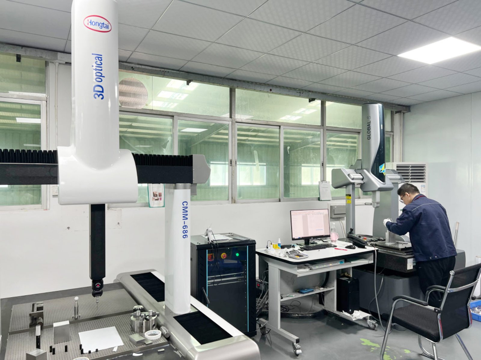
- Final inspection: parts are measured on a CMM against the drawing, with dimensional reports, and for automotive work the full APQP/PPAP package including first-article inspection reports.
Three numbers reveal how seriously a shop takes quality. Our targets are Ppk ≥ 1.67 initial on key features and Cpk ≥ 1.33 on general characteristics. Ask any prospective supplier for the same three numbers — if they cannot produce them, they are not measuring, and what is not measured cannot be improved.
Start with the tolerance band, not the capability number. Cpk compares the band to the process spread — it is a ratio, not a badge of accuracy. The recorded example sat on a 0.4 mm length band (76.1–76.5 mm) with Cpk 1.851, which is wide by design. Push that same spread onto a ±0.005 mm feature and it would fail outright. Always ask a supplier for the band, the subgroup size and the window behind any Cpk figure.
Get a Quote for Your Milled Parts
Send your 3D CAD model and drawing for a quote within 48 hours. No minimum order — from one-off prototypes to production runs.
Get a free quote Read the FAQFrequently Asked Questions
What is the smallest tolerance you can mill?
±0.003 mm (milling) / ±0.002 mm (turning) on critical features, confirmed by in-house CMM inspection, with ±0.003 mm (milling) / ±0.002 mm (turning) standard for production.
Can you mill plastics as well as metal?
Yes — POM, PEEK, Nylon, PTFE, and ABS on the same equipment, useful for seals, insulators, and low-friction parts.
What is the difference between climb milling and conventional milling?
Climb milling feeds the work with the cutter rotation and gives a better finish; conventional milling feeds against it. Climb is the default on modern machines.
Why can't an internal corner be square?
Because the cutter is round. An internal corner always carries the radius of the tool, which is why specifying a realistic radius is the single biggest DFM lever.
How many setups does a typical part need?
Most prismatic parts need one to three setups. Every extra setup adds cost and tolerance error, which is why 4- and 5-axis machines are valuable for multi-face parts.
Do you require a minimum order quantity?
No. We accept one-off prototypes and low-volume runs and scale into mass production as your volume grows.
What drawing formats do you accept?
STEP, IGES, STP, DWG, DXF, PDF, and JPG. A 3D STEP file plus a toleranced 2D PDF gives the fastest, most accurate quote.
How do you protect my intellectual property?
Drawings are never shared without written permission, and we sign and return an NDA if you provide one.
What does ISO 2768-f mean on a drawing?
In short, It is a general-tolerance reference. Everything not individually toleranced defaults to the ISO 2768 class named — -f is the fine class (±0.05 mm on a 6–30 mm dimension), -m is medium (±0.1 mm), -c is coarse (±0.2 mm).
Should I choose 6061 or 7075 aluminum?
Pick 6061 for general parts and anything that will be decoratively anodized; pick 7075 for strength where weight matters. 7075 machines nearly as fast but is harder on tools and anodizes to a duller finish, so it usually costs more end to end.
What does Ra 3.2 versus Ra 1.6 mean?
In short, Ra is the average surface roughness in micrometers. Ra 3.2 is a standard milled finish, Ra 1.6 is a finer pass, and Ra 0.8 and below usually needs grinding.
Do you need a 3D file or is a 2D drawing enough?
A 3D STEP or IGES file plus a toleranced 2D drawing gives the fastest, most accurate quote. A 2D drawing alone can work, but every ambiguous feature then becomes a question, and each question adds a day to the quote.
Do you use MIL-STD-105E or ANSI/ASQ Z1.4 sampling inspection?
In short, MIL-STD-105E is the U.S. military sampling inspection standard published in 1989; it specifies acceptable quality limit (AQL) sampling plans for lot-by-lot inspection.
What this shop actually runs
A buyer asking for capability evidence should get a specific answer. The facility behind this guide operates 100+ CNC machines across a 6,800 m2 plant in Dongguan, China, with 100+ staff. The machine list by category:
- 5-axis machining centres (10+) - Mazak VARIAXIS I-600 (510/910/510 mm travel, 12,000 rpm, 22 kW, 71.6 N·m, 30-tool BT40) and Mazak INTEGREX I-250H S (B-axis 0.0001°, 24 kW, 124 N·m, 38-tool HSK-A63). Used on compound-angle parts, single-setup multi-face prismatic work, and aerospace fittings where datum transfer loss is unacceptable.
- 3-axis / 4-axis machining centres (50+) - Brother SPEEDIO S500Z2N / S700Z2N (10,000 rpm, 14/21-tool ATC, 0.7 s tool-to-tool, Z-axis 2.2 G) and Mazak VCE-430A L / VCE-570C L (10,000 rpm, 118 N·m, 24-tool ATC). Used on prismatic parts, plates, brackets, housings.
- Swiss-type turning centres (10+) - Citizen Cincom A20-3F7 (Φ20 mm, 10,000 rpm), TSUGAMI B0206-III / B0205-III (Φ20 mm, 0.1 µm), STAR SR-32JII / SR-32J Type N (Φ32 mm, 8,000 rpm). Used on long, slender rotational parts at ±0.002 mm.
- CNC turning centres (20+) - HEADMAN T70M/1250 (720 mm swing, 117 mm bore, 3,000 rpm, BMT75 12-station turret). Used on shafts, bushings, flanges up to ±0.002 mm.
- Wire EDM (5+) - Sodick AQ535L (550/350/300 mm travel, ±20° taper, 800 kg workpiece). Used on hardened tool steel, internal splines, sharp internal corners that milling cannot reach.
- Inspection: Hexagon CMM + 20+ gauges - Hexagon CMM for coordinate measurement, plus vision system, profilometer, hardness tester, coating thickness gauge, XRF for material verification. The 10:1 rule (gauge 10x more accurate than the band) is applied to every feature.
- Machine highlights - VARIAXIS I-600: one-setup multi-face 5-axis + MAZA-CHECK auto-calibration; INTEGREX I-250H S: DONE-IN-ONE mill-turn, B-axis 0.0001° + Ai thermal shield; SPEEDIO S500Z2N / S700Z2N: Z-axis 2.2 G + 0.7 s ATC; Swiss-type: guide-bush switchable + 0.1 µm resolution.
Tolerance bands held: ±0.003 mm on CNC milling, ±0.002 mm on CNC turning, ±0.002 mm on precision grinding and wire EDM. Capability indices: Ppk >= 1.67 initial on key characteristics; Cpk >= 1.33 ongoing in production.
Certifications: ISO 9001:2015 (116024/A/0001/UK/En), IATF 16949:2016 (131941/A/0001/SM/En, design clause 8.3 excluded - disclosed openly), ISO 14001:2015 (116024/B/0001/UK/En). Certificates are issued to Dongguan Zhuohang Ltd (USCC 91441900MA4UWT6X39, established 2005).
Service area: Austria, Belgium, the Czech Republic, Denmark, France, Germany, Greece, Hungary, Ireland, Italy, the Netherlands, Spain, Sweden and the United Kingdom in Europe; Brazil, Canada, Mexico and the United States in the Americas; China, Israel, Japan, Singapore and Sri Lanka in Asia; Australia and New Zealand in Oceania; and South Africa in Africa. Based in China, serving customers worldwide.
Contact: Felipe Iglesias, [email protected], +86 13126536955.
Standards referenced on this page
- ASTM B211/B211M-19 — Standard Specification for Aluminum-Alloy Rolled or Cold Finished Bar, Rod, and Wire
- ASTM A276/A276M-17 — Standard Specification for Stainless Steel Bars and Shapes
- ISO 9001 — Quality management systems — Requirements